
cutlistlab › Manual › The build guide
Chapter 29
The build guide
A printable guide for your cabinet: cut list, hardware, a drilling plan per part and the assembly step by step, with drawings.
Opening the guide
At the top of the cabinet designer sits the button Build manual, next to What do I need. It opens a new tab with a document calculated entirely from your design: every dimension, every hole and every step belongs to the cabinet on your screen. With Print or PDF you print it or save it as a PDF; the document is laid out for A4.

In a row of cabinets every cabinet gets its own guide: first select the cabinet (its letter), then open the button. A pharmacy pull-out is itself a cabinet in the row and has its own guide; the cabinet around it says in the pull-out step where to find it. The last chapter Cabinet row describes how to join the cabinets.
What is in it
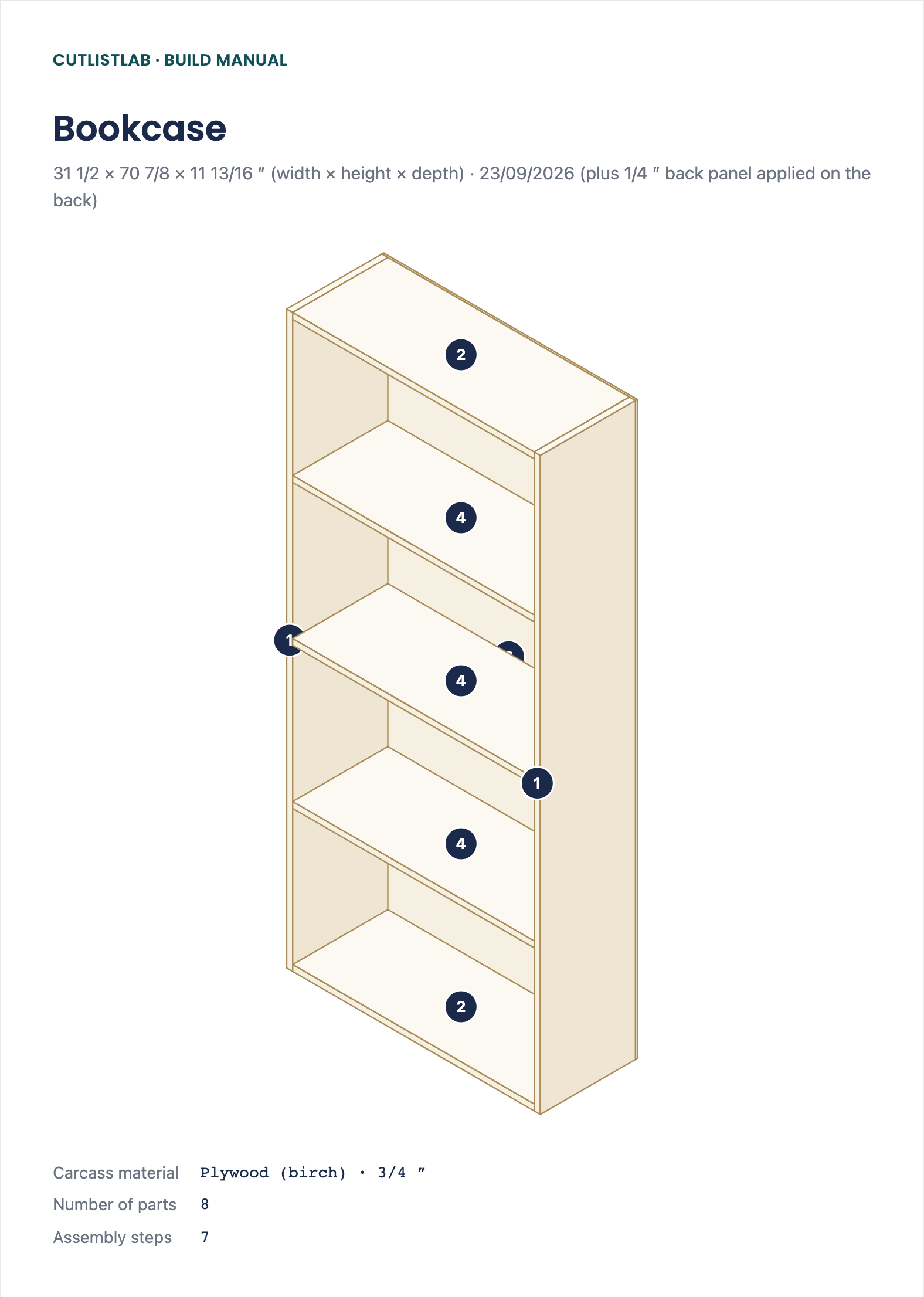
- Materials and cut list
- The same numbers as in the cut list and the cutting plan, with size, thickness, material, quantity and grain direction. Below it Hardware (the same count as in What do I need) and Screws, glue and edge banding: the screws, mounting plates, glue and the metres of edge banding the steps need together.
- Tools
- Derived from what your cabinet needs: a 15 mm Forstner bit is listed only when there are cams, a drilling jig only with a hole line, an iron only with edge banding. Below the list, each drilling jig (hole line, cup hinge, cams, dowels) has a short method with the dimensions of your cabinet and a link to the manufacturer of a common jig. Then Working safely, five fixed rules.
- Joints and hardware: how they work
- The same drawings as behind the i-buttons in the app: how a cam works, where the shelf support sits, the three kinds of cup hinge, the hole line and the slide dimensions of the first drawer. Read this first if the words are new to you.
- Drilling plan per part
- For each part a view with all holes: sides seen from the inside, bottom, top and shelves upside down (the cam housings go into the underside), dividers on their right face, doors from the back, drawer sides from the outside. Dimensions are given as dimension lines along the edges; the legend gives diameter and depth per kind of hole. Grooves and rebates appear as a band. See Common dimensions for the source of those figures.
- Assembly
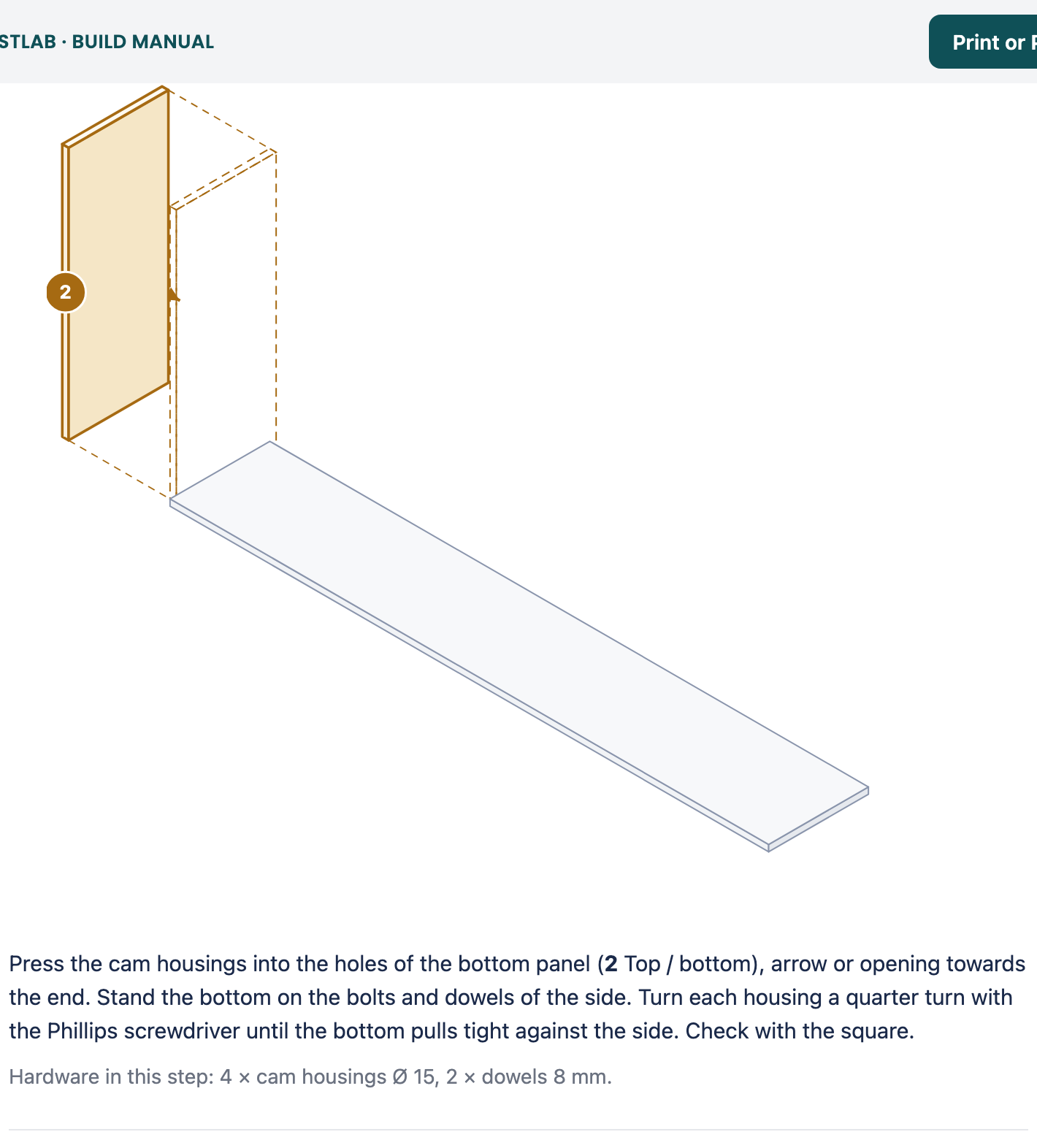
- Step by step, with a drawing per step: the new part in colour, slightly out of place, with dashed lines to where it goes; what is already built is grey. You build the carcass lying on its left side (that is how the drawings show it), then stand the cabinet up for plinth, drawers, shelves, hinges and doors. Below each step is the hardware of that step and, for fronts, the position of each front.
- Adjusting and checking
- The three adjustment screws of a cup hinge, drawers that run skew, the diagonals and the anti-tip fixing. Only the points that apply to your cabinet.
What to watch out for
The guide follows your choices in the app. A shelf on pins gets support holes, a fixed shelf cams or dowels; a drawer with its own false front gets screw holes for the front, a drawer whose front is the front of the box gets dowels; a back panel in a groove or rebate gets a slot in sides, bottom and top. If something does not match what you want to build, change it in the design and open the guide again; the document itself cannot be edited.
Two things are deliberately not in the hardware list of the app but are in the guide: the screws and dowels of drawer boxes, and the cams for a shelf on pins that carries a divider (the guide then says to buy them extra). The frame of a plinth is made of battens and is not in the cut list; the step gives size and number.